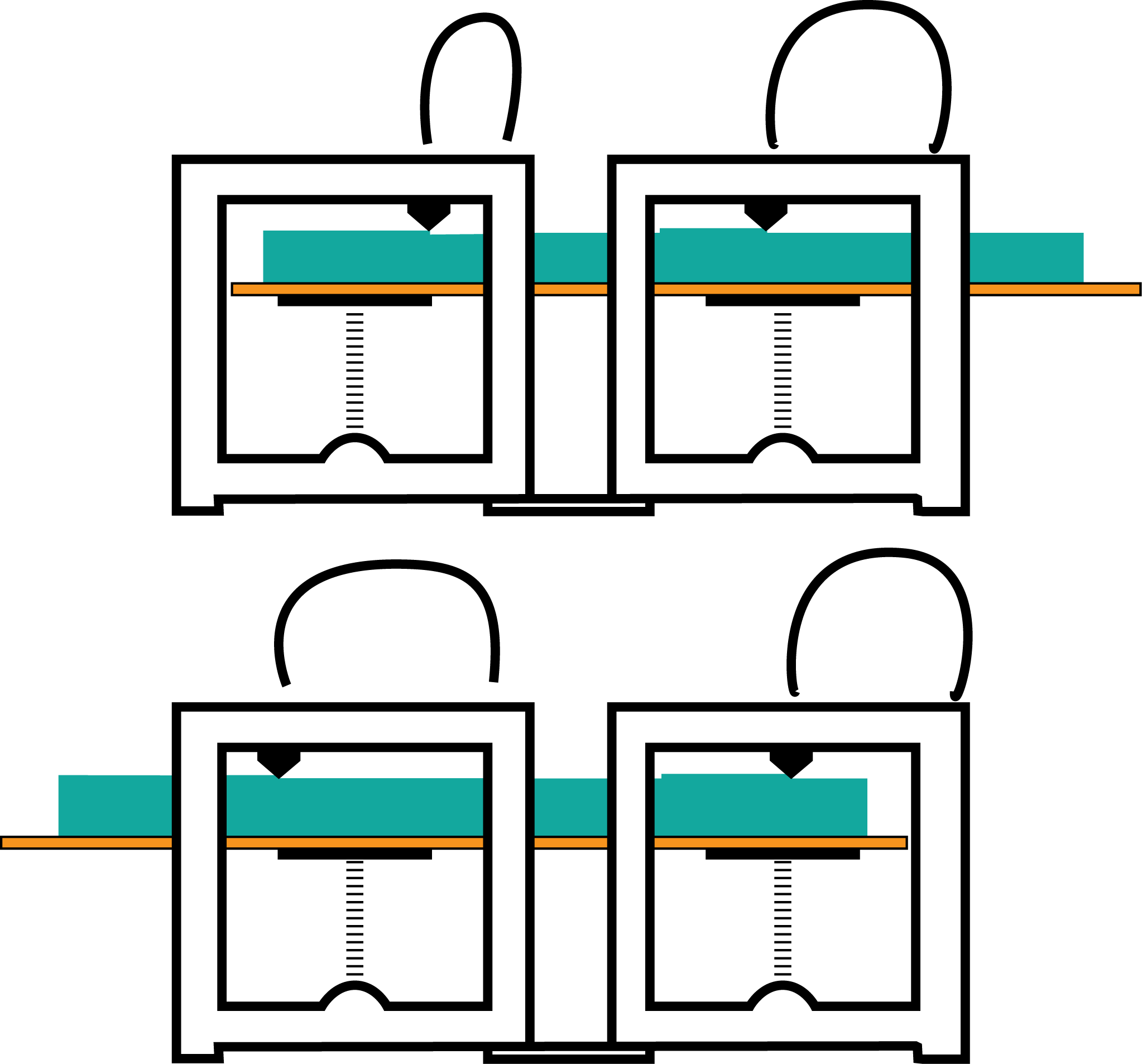
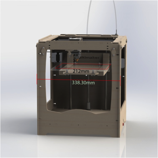
When two Ultimakers are connected and tasked to create a single object, there are some adjustments to be made. The standard Ultimaker x/y-frame gives the nozzle a range of 212×212 mm. The table on which a product is printed is dimensioned slightly larger to allow space to bolt the table in place on the z-directional guided platform.
As seen in the illustration above, the range of the nozzle differs from the width of the Ultimaker housing. Because of this, coupled Ultimakers can’t have overlapping or meeting ranges.
To extend the range of the nozzles the printing platforms have to be altered. The product that is being made by the printers has to be built on a single surface, consisting of the two nozzle ranges and the distance between these ranges.
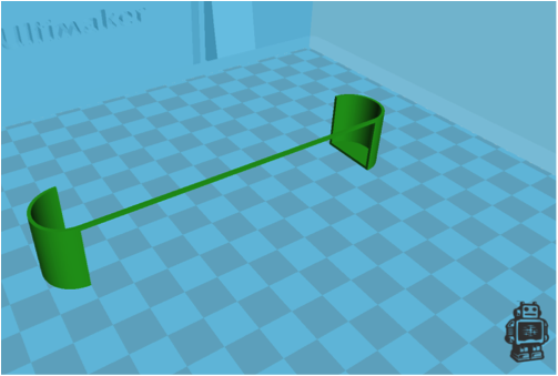
We have designed a table that is able of sliding in the x-direction (left-right in a frontal view). To test the principle of this table we conducted tests using one Ultimaker where the standard Perspex platform was substituted by our larger table. We printed one model that was split in two, giving us time to move the table between every layer, making the two halves into one object.
With the test we sought to find out if printing a product in two stages creates problems at the point where the two stages connect. We used the following file for our test.
The following image shows the basic principle of printing with a sliding table:
Footage of this test is seen here:
[youtube]http://youtu.be/FL67qibS8ig[/youtube]
The moving table in this test model is made of 3 mm MDF which wasn’t strong enough. This table allowed a small amount of twisting which, in large product, could become problematic. Also this table was not fit for automatic movement. As seen in the video the table had to be moved by hand.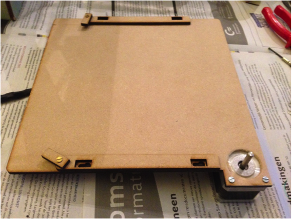
To control he movement of the table another motor is used. Ultimakers already have four of these motor in their systems. This motor needs to be attached to the new custom platform. This motor will be fitted with a gear and the table will be fitted with a rack.
The motor attached to the new base platform that will operate as guidance for the printing platform.
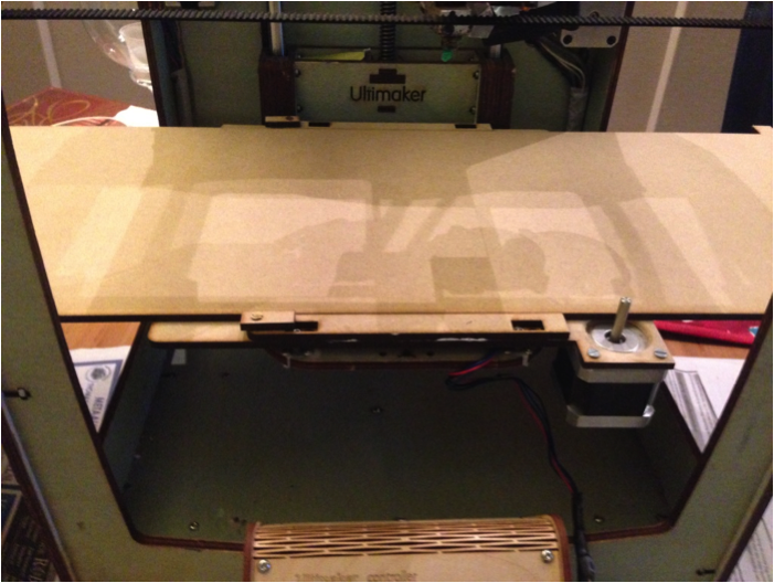
The base attached to the ultimaker, with the building platform placed in it.
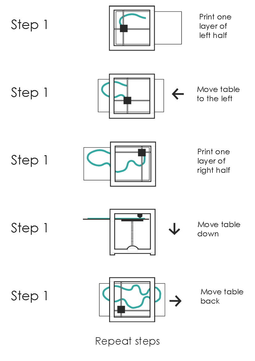
Eventually we want to print the splitted object with two nozzles (two Ultimakers). The printing process would look like this: